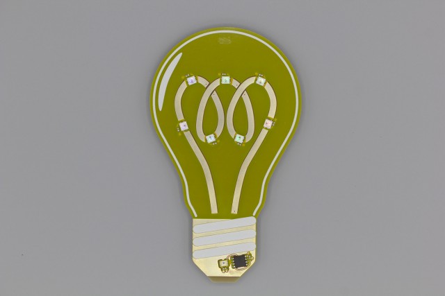
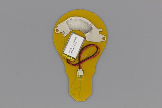
As part of a Halloween costume (I was a “bright idea”), I designed a light bulb PCB, which was mostly just an excuse to try out PCBmodE. It consists of seven addressable RGB LEDs, an ATtiny85 microcontroller, an ambient light sensor, and a rechargeable battery. The battery and an old hard drive magnet, for mounting the PCB, are attached to the back via double-sided tape. As one might expect, PCBmodeE worked well for this artistic circuit board design, given that it was designed to be used for something like this, but KiCad is much easier to use for just about everything else.
The ambient light sensor proved less useful than I had hoped—the LEDs were too bright to use with all but their dimmest settings, and the light sensor’s optimal range didn’t align well with the lightning levels I was interested in. I also should have placed a copper pour behind the soldermask for the majority of the bulb, since it would have made for a better yellow color. Finally, the footprint I made for the microcontroller footprint is too narrow, but it’s close enough that I was still able to solder the microcontroller in place; a slightly wider footprint for the ambient light sensor would have also made soldering easier. Since this was a one-off, and it’s now past Halloween, there’s no reason for me to revise the PCB to fix these shortcomings.
The design files are in a GitHub repository.

