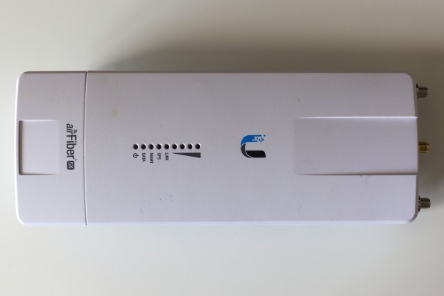
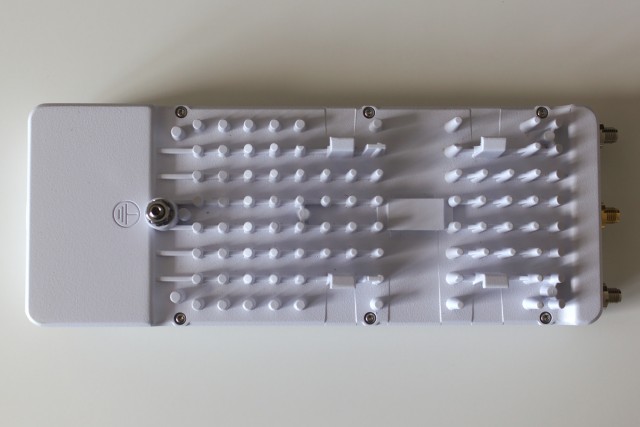
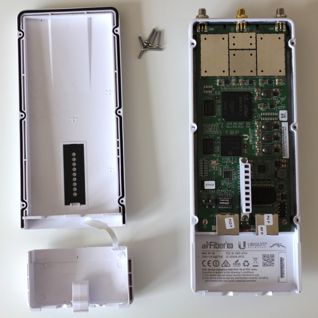
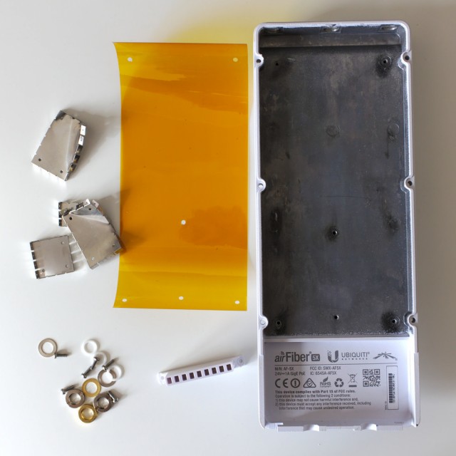
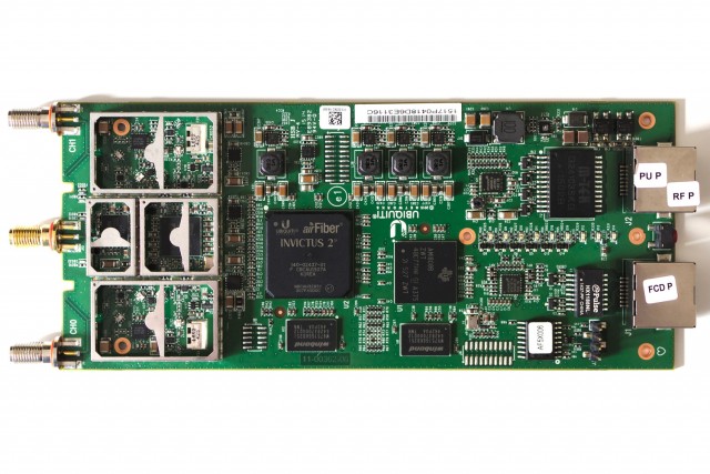
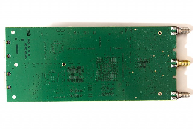
I recently came across a malfunctioning Ubiquiti airFiber 5X radio, so I decided to take it apart. The radio’s case can be opened by removing six T6 screws on the back. The PCB can then be removed by unscrewing six Phillips #1 screws, two of which are under the RF shields, and by removing the parts that secure the RF connectors to the case. The front part of the case is plastic, while the back part is aluminum; there is a gasket where the two case parts join and around the RF connectors. A polyimide film insulates the PCB from the aluminum case back.
Components on the PCB include an ARM9 processor (TI AM1808B) with 512Mbit of DDR2 SDRAM (Winbond W9751G6KB25I) and 128Mbit of flash memory (Winbond W25Q128FV), an Invictus 2 ASIC with 512Mbit of DDR2 SDRAM (Winbond W9751G6KB25I), a pair of RF transceivers (Analog Devices AD9361BBCZ), a pair of 5GHz WLAN power amplifiers (Anadigics AWL5910), and a GPS receiver (u-blox AMY-6M). For the data Ethernet port there is an Atheros AR8035 gigabit Ethernet transceiver and M-TEK G24103SKG magnetics, while for the management Ethernet port there is an Atheros AR8032 fast Ethernet transceiver and Pulse HX1188NL magnetics.
