Your average consumer scanner works well for scanning normal printed or handwritten documents, usually anything up to Letter or A4 size. For something a bit larger, say Legal or Tabloid size, one can try to scan the document in segments, but the scanner’s lip, which is great for aligning smaller documents, becomes a major hindrance, and one usually resorts to scanning the document using a copy machine if one has access to one. This is fine until one has a document that is too big for a copy machine, e.g. what I wanted to scan—old maps. They’re too big to fit in a scanner or copy machine even if one tried to fit part in at a time; besides, one shouldn’t try that since they’re old and irreplaceable. One could photography them, but one needs a scanning back camera to get anywhere near comparable resolution, which are really expensive. That is where this modification comes in—modifying a low-cost, off-the-shelf consumer scanner to scan arbitrarily large documents in segments, which are then assembled via software.
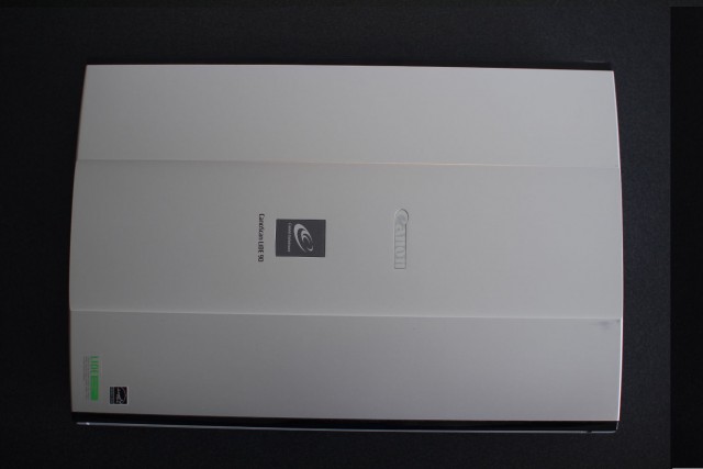
We start with a Canon LiDE 90 scanner, although any scanner in the Canon LiDE series will do as they’re all similar.
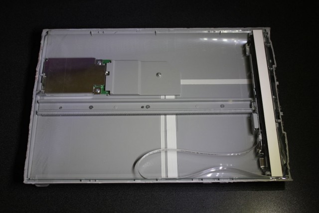
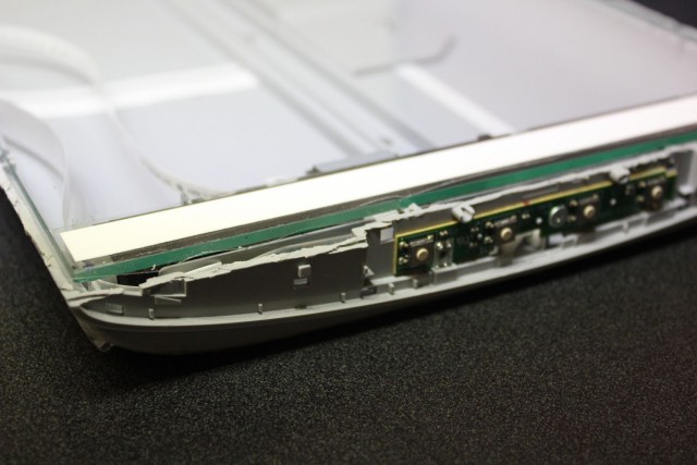
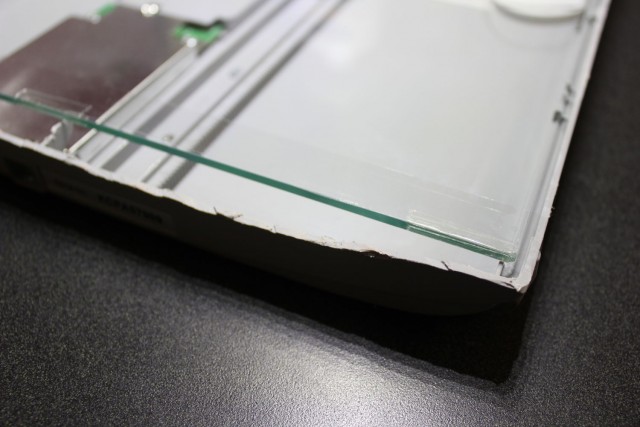
First, we need to remove the lid, which can be done without too much effort by pushing on the center of the piece of plastic that connects the lid to the hinge on the scanner. Next, the lip around the scan glass needs to be removed. It is attached with small plastic tabs as well as adhesive near where the control buttons are. Since we won’t be needing this anymore, it’s easiest just to pry this off. With the lid and bezel removed, observe where plastic still sticks up above the scan glass; then, carefully remove the scan glass, and put it in a safe place. Next, using whatever cutting tools seem appropriate, cut away the rest of the plastic that sticks above the glass, being careful not to cut oneself or cut away the plastic that the scan glass rests on. For this, I used a small cut-off wheel and a razor blade. Now replace the scan glass, making sure it is free of dirt and fingerprints. During disassembly, one should have noticed that the back of the bezel piece that was glued to the glass was white; this is for calibration and needs to be replaced by cutting a strip of photo paper the same size. Place the strip of photo paper above where the scan element’s home position is, printable size down. Finally, tape this strip and both end of the glass to the scanner using strips of packing tape.
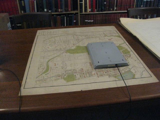
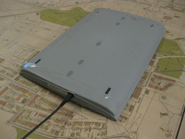
One is left with a scanner that can lie flush, glass-down on a table.
To scan large documents using the modified scanner, place the document face-up on a flat surface. Then, place the scanner glass-down on top of the document and scan it in segments, ensuring sufficient overlap between scans.
Finally, stitch the scanned segments together. Recommended methods include following a tutorial using Hugin or using a script I wrote to try to automate the process.
Here is a result of the process—a 1915 map of the Homewood area of Baltimore. The map was scanned in 20 segments at 600dpi, resulting in a final image resolution of just under 500 megapixel.
Thank you to Paul Espinosa at the George Peabody Library for letting me scan the map from their collection.
Pingback: Hacking a flatbed scanner to scan very large documents
An excelent idea nicely explained! Thanks!
Looks like an awful lot of dust is going to get below the screen and on the sensor strip?
It is a concern. I keep the scanner in a bag to help mitigate the risk. The glass is only held on by two strips of tape, so it’s fairly easy to remove and clean.
Pingback: Scan Large Documents | WebBlog
My god, this is BRILLIANT. I work in a department where we have VERY large blueprints from decades ago that are falling apart but we absolutely need to keep them for reference… Now we can scan them into a gigantic picture, and then send the origonals off to be put into long term storage.
I think the only change I am going to make is to seal up between the glass and the mechanical insides. Maybe put a handle on the sides for ease of moving it around.
Have you seen the FlipPal Mobile scanner? Its battery operated, portable, 4×6 scanner with open back, so that you can use it in a similar fashion, but see where your overlapped sections are. Saves each scan to an SD card. So you don’t have to have it connected to the pc while doing the scanning. Only drawback is the number of scans it would take to do such a large format item. But I’d love to see a full size scanner made the same way. Question on your stitching the images — with a huge document like that, doesn’t it take more processing power on your computer? How do you handle the bigger and bigger file size that is created?
As a previous commenter pointed out, HP used to make the Scanjet 4600, which is full-sized with a window. I was able to buy one used off eBay, but it uses plastic instead of glass, so the platen scratches, and it requires external power. It would be great if a company made a full-size bus-powered scanner with a glass platen, but I don’t know of any that do. It does take a large amount of processing power and memory to stitch the scans, but I have a high-end desktop computer, so it isn’t much of an issue for me. It still takes a long time, but it’s automated. Disk space isn’t much of issue as a high quality JPEG of the results is only about 150MB.
As a newbie to both Python scripts AND Hugin, I have just tried to use your script.
Apparently I don’t know how to use it – the script returns -11 – but I have no idea what it means!
Is it meant to be run from within Hugin? This is what I did, after having the images brought into Hugin.
Sorry, but can you help a noob out here? Tell me how to use the script?
I have 72 scans making up four sheets of actual paper, and am desperate to make real assembled images!
I have no idea where that error is coming from. Normal usage is
python stitch-scanned-images.py img1.jpg img2.jpg img3.jpg imgN.jpg. If it doesn’t work for you, I’d recommend using Hugin and following this tutorial.I tried flipping my Epson scanner upside down and it made horrible noises. Do you know what features to look for to ensure that it can scan flipped upside down? Do all Canon LiDE models have this capability?
I think it has to do with the weight of the scanning module, but as I haven’t tried it with any other scanners, I’m not sure. All the Canon LiDE models I’ve seen have been built pretty much the same way, so I assume any of them should work.
Just finished the modification on a used Lide 90. Sealed edges with tape.
seems to be working well. I use Photoshop Elements 11 auto stitching
called auto panorama. I used the interactive mode and worked to
perfection. I had to scan in my Photoshop 7 because Elements hasn’t
recognized the scanner yet. Will post more as I scan more.
Thank you Matthew
Thanks very much for this script – I was struggling to do this manually in Hugin, failing to understand what I’m doing – now this script pretty much does it all for me.
However, I have a few cases (I have a collection of about 20 large collage scan sets of this kind that have been hanging on my disk waiting to find a way to put them back together) where the result isn’t quite right. Mostly these are only a matter of cropping too tightly – I’ve also got one case where it’s applying some weird distortion to one of the tiles, presumably because it’s misidentified some control points.
I can just about manage to deal with the cropping by editing the .pto output by this script to use the original filenames instead of the temp ones, then opening in Hugin and adjusting the cropping. But I’m such a Hugin noob that I’m terrified that I’m doing it wrong (when I use the horizontal scrollbar in the preview window to do it visually, is that distorting it? If I enter numbers in the Stitcher tab of the main window, should I just adjust the crop, or do I need to adjust the canvas size as well, and what about the field of view?)
Is there an easy way to tweak the script that it crops more conservatively, leaving me to do an exact crop in an ordinary image editor?
Or failing that, can you give a noob a clue about the right way to edit it in Hugin?
Also, I assume there’s a reason why the script generates temp files, so will I be introducing distortion by editing the .pto to reference the original files instead? Would I do better to edit the script to store the temp files somewhere they won’t be automatically cleaned up?
Many thanks in advance for any advice.
Using the slider in the preview window adjusts the field of view, which doesn’t distort the image. The crop is Hugin’s auto crop, which doesn’t have adjustable parameters. The script creates temporary files because it distorts the images such that all the control points line up exactly, which can lead to strange artifacts if some of the control points are too far off. The easiest way to edit things before the mosaic is stitched is to add the line
input('Press enter to continue...')between lines 141 and 142, which will pause the script just before the stitching process begins, giving you time to edit things.Canoscan LiDE 110 made this a very frustrating project to me, when I did the same half a year ago.
The white calibration strip has two black marks, one horizontal towards the far end of the scanner, and 3 small marks at the left edge, which I found to be extremely crucial to have the scanner functioning.
If the marks are gone, the scanner head doesn’t advance very far, and only gives an error that you need to release the lock.
I even tried to flip the strip around and still display the black marks in another place, but no change.
The placing is also very crucial, a few millimeters aside and you just get the same error about releasing the lock.
Interestingly, after the scanner has done its calibration with the green light and started to scan with the normal RGB-light, the scanner happily continues to scan anything even after the strip has been removed.
I’m using the Canon MP Navigator EX on Windows, could a different driver bypass the calibration somehow?
I’m not sure. SANE might work, but it doesn’t run on Windows.
Pingback: How to Scan Oversize Images with a Flatbed Scanner
Pingback: Scanning Patterns | Ninth and Adams
Oh no! I’m nearly done removing the plastic sticking up and the scanner head fell out. I can see how most everything goes back together, but I have this yellowish gold ribbon that is no longer attached to the white hanging tab to the right of the metal rectangle on the scanner head facing the back of the scanner. Don’t suppose you can send a detail photo of that area which shows where the gold ribbon attaches?
thanks!
http://imgur.com/a/FPXaX
Quick update: I *think* I got the scanner head and ribbons back together correctly with the white tabs. I will report back once I can pick up some goo gone (likely tomorrow) to remove some adhesive left by the calibration strip. Once I do that and attach a strip of photo paper I should be able to test and report back.
Cheers!
Matthew, thank you so much!!
Out of curiosity do you think matte or gloss photo paper is best for the strip? I need to pick it up.
As a side note the family will be so happy when I can scan in some 7’x4′ and other large family tree diagrams my late grandfather drew on graphing paper some 15+ years ago. They are aging and will be so nice for family research once digitized.
Thanks!
I don’t think it really matters since the paper is attached directly to the glass. If I had to pick one, I’d go with matte as the strip it is replacing isn’t glossy.
Matthew, I forgot to write back to say that this worked great! Thank you so very much! I’ve been able to preserve some very old family tree’s that my grandfather created in his later years that I didn’t acquire until around 15 years after he had passed.
So thank you!
Picked up the scanner in a thrift shop for $1.50, followed your tutorial, and it works slick.
I picked up a CanoScan LiDE200 from eBay for a good price and it took awhile to figure out that there is a very small area on the edge of the calibration strip that needs to be black that exists on the plastic strip that I removed for the unit to calibrate. I took care of that with a Sharpie, in case anyone else encounters a similar calibration error.
But I am having problems with errors in running your code under Win7 x64. When morphing the images (specifically, image 7 of 15), I get a Windows error that the filename or the extension is too long. I realize that you published this a couple of years ago and have since moved on, but can you reveal under what conditions you achieved your success (operating system version, Python version, Hugin version) so that I can try to reproduce that environment?
Thanks! Great project, by the way!
I’ve used it with Windows XP and a couple Linux distros with Python 3.3 and I think Hugin 2013.0.0. I don’t use Windows anymore, so I can’t be of much help for dealing with its command line idiosyncrasies. Sorry.
Hey, you did good! The partial results I’ve been able to achieve from Hugin so far have been superb, significantly better than those from PhotoMerge in Photoshop CC, so I’ll keep trying.
It’s encouraging to see your name on the Windows builds of the pano tools in Hugin 2013.0.0, so there is no doubt in my mind that your script works.
I’ll fire up one of my WinXP VMs and give it a whirl. Again, thanks, Matthew!
Thank you for this article!
Trying this with an LiDE120. Overcame the calibration issues by recreating the strip with black marks in InDesign, printing out to size, and messing around with the placement until it worked.
At this point I’ve run into a different issue: Scanner works fine when right-side up, but when I flip it upside down and scan, the produced images are just completely black. I tried scanning upside down with one side over the edge of the table (to check that it was still lighting up) and it is… Any ideas as to why these upside down scans are coming out black?
It sort of sounds like a calibration issue, but I really have no idea. Sorry.
I modified a LiDE 220 and every once in a while it start scanning black picture. I figured that it has something to do with the calibration and start working again after moving it or pushing it around. When it start scanning black picture, if I unplug it and replug it, I get the typical error to put the lock switch in the unlock position and to disconnect and reconnect it (like when the strip was misaligned). It’s frustrating as mine was sealed with caulking and taped in place so it is hard to move the glass around but it does that every once in a while and then start working again after I start losing patience. It’s too bad because it work so well for a while and then stop working for 10 minutes like that. If only there was a way to hack the driver to ignore the calibration strip…
Hi there. Do any of you have one of these for sale, please? Or would be willing to build me a custom model? I need to scan about 200 large drawings for my book and don’t have the time or ability to to this myself.
I’d like one with a larger scanning area so I can reduce the number of scans to save time. What scanner would you recommend to modify for widths of just under 30 inches? Would it be possible to hire you to build me one?
I don’t have a recommendation. Sorry.
Hi Steve. I have exactly the same question and was wondering whether you managed to get hold of a scanner to suit your needs? I need to scan about 200 drawings of sizes from A2 to A0 for a book.
What program did you use for zooming in/out the map after scanning it?
OpenSeadragon
Thanks Matthew for this tutorial – just looking at Canon LiDe scanners on eBay now – would the 100, 110, 200, or 220 ones work for this modification? I’d like to scan large artworks.
The Canon scanners all share a similar design, so they would probably work.
Wouldn’t the packing tape show up in the scans? I’m trying to do this now. Dust kept getting inside my scanner. I’m not sure a glue gun would work to fill the gap between the glass and the side.
The tape goes where the plastic bezel was originally, so it doesn’t appear in the scans. Dust, however, can be a bit of an issue.
Thank you so much for this post. I needed a scanner to scan my large paintings. Followed your post and modified a CanoScan Lide 220. It works! It took me a while to get the scanner to work though. The 220 has a calibration strip with 3 dots on one side and a stripe in the center. The replacement strip I had cut out didn’t, of course, so I was getting an error message. What I did was I reused the original calibration strip (yes, it was a bit wrinkly) and tried many times to place it in the right spot. Once the scanner was able to calibrate, it is working fine!
Very nice, thank you for sharing! I came up with the same idea while trying to scan big game board and found your page by accident. I had two potential plans, either build a pick and place-like rig with pvc and such to hold a camera (with level) that would let me move it in all four direction and take precise top-down shot or shave/sand the edge of my Canon lid220 scanner to make it flush. The rig would have been much more time consuming and your post just proved me the viability and superiority of my second plan:) It is going to be much nicer since I can scan 1200dpi 48bit color with the scanner and stitching the pic together with your script seem to give very good result, much more than the tests I made with different software.
Hi Matthew,
Many thanks for sharing your method, which inspired me to undertake a similar project – with the difference that I wanted to lay the artworks (mostly my old oil paintings) onto the scanner, rather than the other way around. This meant that I needed to sink the scanner into a flat surface that would be flush with the glass.
I decided to use an Epson scanner – the relatively cheap Perfection V39 – as I already use Epson scanners and I’m familiar with their software and quirks. Also, I could see from Amazon that the V39 appeared to have a separate plastic frame for the section above the glass, which I thought might make its removal easier – which did turn out to be the case, though it’s not completely straightforward.
Anyway the project has been very successful. I was expecting that the scan quality would not be as good as my more expensive scanner, but at 800 dpi there is very little difference – the colour response is not quite the same, as my other scanner uses a fluorescent tube, but the color is easily adjusted in Photoshop. I’ve been using Microsoft ICE to stitch the pictures, and I have to say it has worked flawlessly.
I’ve put a few photos onto Dropbox:
https://www.dropbox.com/sh/obreetb3u765osi/AABvQrir5Rfmvraa5PZvMIwQa?dl=0
The pictures show the deconstruction of the scanner and the incorporation into a ‘scanning table’ at various stages. I can supply more details if anyone is interested.
Hi Mike, I’d really love to know more… can I message you privately? I have the same scanner as you and need to start scanning large paintings for my inventory and online print shop. I’m curious about the wood table you made for your scanner, and how you cut it all out! Thinking my boyfriend may be able to help me with this… hoping it’s a doable project!
I’m happy to help you any way I can. Let me put together some info for you and get back to you.
Hello Mike,
Superb work on the table and the mods to the v39. I have been using Matthew’s design for a couple of years to scan my wife’s work and also find the image composite editor to be my best friend. I have tried many other stitching programs, but ICE is certainly my current favorite.
I was wondering if you might allow me to ask you a few questions about the scan table and how I might be able to build something similar but with either an 11×17 scanner or an extremely modified series of A4 scanners that can be laid in pairs for a very large scan table.
Sincerely appreciate your time and have also left a comment on one of the DB uploads you made.
Thank you,
WM
Hi
Thanks for this tutorial! I thought i would give it a go so got hold of a V39 this week.
Excellent instructions and if anyone is wondering about how to release the middle part of the end bevel – away from the scanner head – then there is just another screw underneath the unit.
Unfortunately…I just can’t get the calibration right. Scans always has faint vertical lines unless I re install the scanner head end bevel with the calibration strip – then it works fine.
So – any tips on fitting the calibration strip would be greatly appreciated – after two days messing around and numerous attempts.
Should i print it on photo paper? – or ?
thanks again for a great suggestion/tutorial
Matthew,
Many thanks for this idea. I found this a couple of years ago and attempted the scanner mod and have cycled through at least 4 different scanners over the years using your method. I have been meaning to come back and leave a thank you.
Take care!
Thanks so much to Matthew and to Mike!! After receiving my V39 last week — so disappointed to see the raised rim… now I know what to do. (My aged HP 4600 finally has too many missing scan pixels to work; Doxie 4×6 needs too much stitching for my larger artwork and historical maps).
I hope it works for you! All the best – Mike.
Nancy, planning to do something similar. Did the V39 work for you?
Matthew,
Thank you so much for spending the time to share this POWERFUL modification with us all. Now I can finally scan big documents, photos, maps without the hassle of those bezels.
I must say it took some culture shock to rip off end caps, bezels, lift glass and then !! with great noise and heat !! cut-wheel off the plastic.
I felt after all the sturm and drang that in no way would this fragile scanner work again. But it did.
I too was working with an LIDE 110. By reading comments I knew to reuse the white calibration strip – peeling it from its plastic holder (easy to do). I taped that orginal on. It took a few tries with the strip — up and down left right before the scanner was happy (got unlock and error messages for the first 5 tries or so) but it finally worked.
Wonderful help.
THanks,
John Daly
Thanks! Almost nine years later I needed this functionality, found your guide, bought a used old Lide 110 and followed the instructions. It works great! Now I just got figure Hugin out. :)
I had the same idea and I thought – I cannot be the first one to think that way; I googled and found this article. I cannot find the scanner you mentioned; I’ll try it with some other. And now I wonder, why don’t Canon, Epson, HP or any other company make scanners that are made for this kind of scans; it’s not complicated!
Thanks Matthew for this tutorial. Would such a scanner allow additional modification so that scanning could be done at the very edge of the glass? That is, so that the scanning area starts at the very edge?
No, that isn’t possible, at least not without cutting the glass. In these scanners, the sensor carriage is springloaded against and slides along the back surface of the glass at the edges parallel to the movement direction, to keep it appropriately spaced and parallel to the front surface of the glass where the document is. Thus, the only way to have scanning start at the very edge of the glass would be to notch the glass such that the sensor element can start at the edge of the notched area, while the end of the sensor carriage are still supported by sections of glass that protrude at the edges parallel to the movement direction.
Am I right in thinking that when you talk about the ability to cut the glass without compromising performance, you are referring to the area marked in red in the following screen? — https://i.imgur.com/HOcGq0U.jpeg
I need this feature to try a V-shaped scanner design, where the scanner would be at a tilt and scan the right or left page of a book half-open underneath. And therefore need the scanner to be as close to the inside of the book as possible. The idea is to automate such a design over time.
(Sorry my english)
No, I’m referring to the side perpendicular to that. The area you marked in the area where the sensor carriage presses against the glass, so there’s no way to remove that.
Thanks for the idea! However, I just tried this on a Lide 200 and there is definite warping to each scan. I’ve compared three identical scans without moving the unit just to make sure. I also have an extra spring and I can’t figure out where it came from. I found it rolling around in the bed when I was cutting the plastic. Hopefully that’s not my issue.
There are two springs (if I remember correctly) in the sensor carriage, one on each end, for pressing the sensor assembly against the glass. If you’re missing one of the springs, the sensor won’t be parallel to the glass, which could cause the warping you’re seeing. The white plastic parts at the ends of the sensor carriage should both be pressed against the glass.
There isn’t any “hardware” calibration in the Canon LiDE scanner models (except for the newer 300 and 400 models). Everything is handled in the driver / scanning software. About all the scanner itself is capable of is to receive sensor configuration and motor movement commands and to return lines of data from the sensor. The calibration is done in software and wouldn’t explain the issue you’re seeing.
Also, I’m using Vuescan which somehow bypasses the hardware calibration. I don’t even have the paper strip on the glass. Perhaps that’s causing an alignment issue? I’m just guessing here. I did end up calibrating with vuescan and an it8 target, but I’m second guessing the results with all the issues that I’m having.