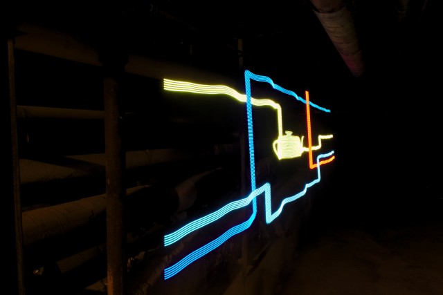
A digital light wand, used to paint images in long exposure photography, has been around for a few years, since the advent of cheap, controllable RGB LEDs. While there are freely available designs and code for such a device, I wasn’t happy with them, so I decided to design and build my own. The control electronics for the design I looked at used a Arduino Mega 2560, with a display and control shield as well as other components; I found this far too bulky. Furthermore, the design used a grossly underpowered voltage regulator rated for 1A with a strip of LEDs that draws upwards of 2.5A. The LED strip, however, is one of the nicest ones available, with 144 individually controllable WS2812B RGB LEDs on a one meter strip.
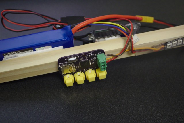
To this end, I designed a small, minimal board around the Freescale ARM chip used in the Teensy 3.1, due to the very nice WS2812B library available for it. For power, I used a 20A regulator to ensure enough current and a rechargeable lithium polymer battery to avoid eating through disposable alkaline cells.
A Python script is used to convert an image into a binary file and add start delay and display rate information. The file is then loaded onto a micro SD card and named to fit into one of four slots, corresponding to the control board’s four buttons for displaying images.
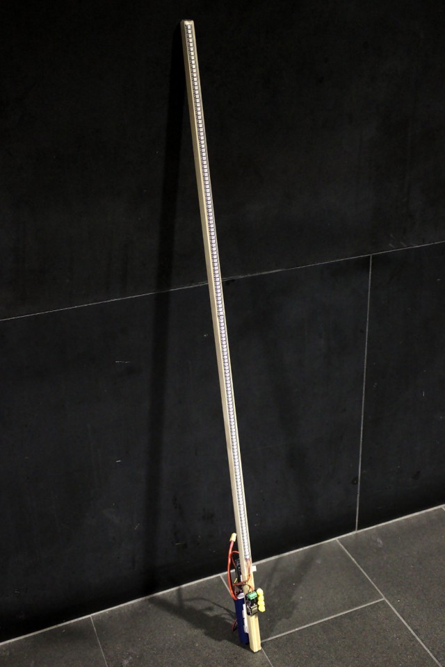
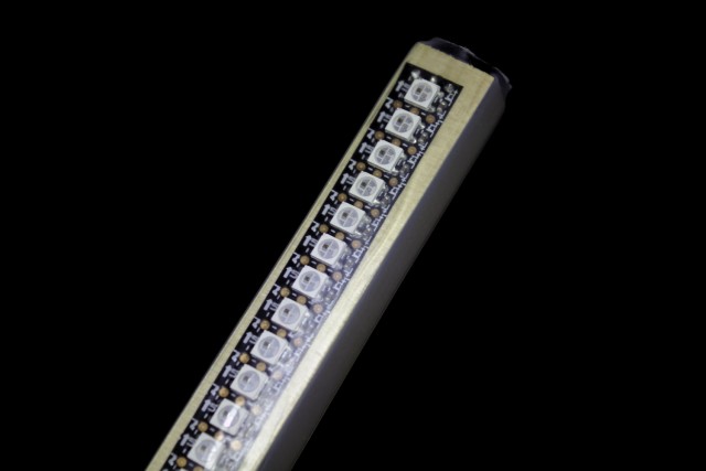
The one meter LED strip is actually two 50cm strips soldered together, due to manufacturing limitations for flexible PCBs, which leads to a noticeable gap where the two parts are joined. I was able to narrow this gap by resoldering the parts together by stacking them instead of them just abutting, but the gap is not completely gone. Additionally, I damaged one of the LEDs at the joint in the process and had to replace it. I then mounted the strip on a four foot section of 3/4″ square oak molding with clear heat shrink tubing and mounted the control electronics and power supply using interlocking fasteners.
 Designs and code are available from a GitHub repository.
While I felt it had some shortcomings, Michael Ross’s design is much better documented and easier to build. As much as it irks me to see development boards used in final products, I’ll concede that they make things much easier for those without extensive soldering experience. However, his design’s power supply is inadequate, and one should really use something rated for more power.
